If you want full control over a TM1637-based LED display and key scan driver, the TM1637Titan
library gives you both high-level convenience and low-level access. In this guide, we will walk through the
library structure, show how to initialize it, explain the most important functions, and build practical examples
you can use in real projects.
DOWNLOAD LIBRARY
What is the TM1637Titan library?
TM1637Titan is an Arduino library written for the TM1637 LED driver IC. It is designed to expose
nearly all core chip features, including:
- Display on/off control
- Brightness and duty configuration
- Automatic address increment mode
- Fixed-address writes
- Direct display RAM access
- Raw key scan reading
- Decoded key handling
That means you can use it either as a simple display driver or as a more complete interface for projects that need LEDs and buttons together.
Library file structure
TM1637Titan/
├── TM1637Titan.h
├── TM1637Titan.cpp
├── README.md
└── examples/
    └── FullFeatureDemo/
        └── FullFeatureDemo.ino
The .h file contains the public API, constants, and class declaration.
The .cpp file contains the implementation.
The example sketch demonstrates how each important function works.
Installation
- Copy the
TM1637Titanfolder into your Arduinolibrariesdirectory. - Restart the Arduino IDE.
- Open the example sketch or include the library manually in your own project.
#include <TM1637Titan.h>Basic wiring
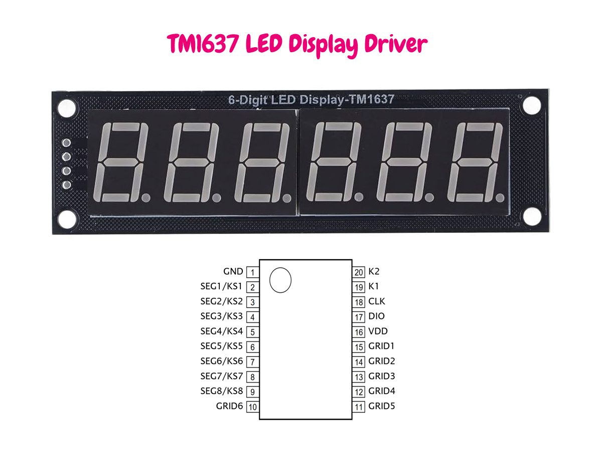
The TM1637 uses a 2-wire serial interface. You only need two MCU pins:
| TM1637 Pin | Arduino | Description |
|---|---|---|
| CLK | Any digital output pin | Clock line |
| DIO | Any digital I/O pin | Bidirectional data line |
| VCC | 5V or module-rated supply | Power |
| GND | GND | Ground |
Creating the object
First, create a library object with the clock and data pins you want to use.
#include <TM1637Titan.h>

TM1637Titan display(2, 3);  // CLK = 2, DIO = 3
In setup(), initialize the driver and turn the display on.
void setup() {
  display.begin();
  display.setDisplayOn(true);
  display.setBrightness(7);
}
Your first output
The easiest way to write to the module is to send raw segment data into the TM1637 display RAM. A typical 4-digit module still sits on top of the chip's internal memory structure, so the library lets you control bytes directly.
uint8_t buffer[6] = {
  0x3F, // 0
  0x06, // 1
  0x5B, // 2
  0x4F, // 3
  0x00,
  0x00
};

display.writeBytes(buffer, 6);
This method is ideal when you want full flexibility and already know the segment bit patterns.
Core functions you will use most often
1) begin()
Initializes the interface pins and prepares the driver.
display.begin();2) setDisplayOn(bool on)
Turns the LED output on or off without clearing RAM.
display.setDisplayOn(true);
display.setDisplayOn(false);
3) setBrightness(uint8_t level)
Sets brightness level from 0 to 7.
display.setBrightness(0); // minimum
display.setBrightness(7); // maximum
4) clear()
Clears the display RAM used by the module.
display.clear();5) writeByte(address, data)
Writes one byte to a specific RAM address.
display.writeByte(0xC0, 0x3F);6) writeBytes(data, length)
Writes multiple bytes in auto-increment mode.
uint8_t data[4] = {0x3F, 0x06, 0x5B, 0x4F};
display.writeBytes(data, 4);
7) readKeysRaw()
Reads the raw key scan bytes returned by the chip.
uint8_t keys[4];
display.readKeysRaw(keys);
8) decodeKey()
Converts the raw scan result into a simplified key identifier.
int key = display.decodeKey();
if (key >= 0) {
  Serial.print("Key pressed: ");
  Serial.println(key);
}
Understanding addressing
One of the useful features of the library is the ability to switch between auto increment and fixed-address writes. This matters when you want either fast sequential updates or precise single-byte control.
Use fixed address mode when changing only one digit or indicator.
// Write a full buffer quickly
uint8_t frame[6] = {0x3F, 0x06, 0x5B, 0x4F, 0x66, 0x6D};
display.writeBytes(frame, 6);

// Update a single RAM position
display.writeByte(0xC2, 0x5B);
Reading keys
If your TM1637 hardware includes buttons connected to the key scan matrix, the library can read them directly. This is especially useful for menus, counters, timers, and compact user interfaces.
void loop() {
  int key = display.decodeKey();

  if (key >= 0) {
    Serial.print("Detected key: ");
    Serial.println(key);
  }

  delay(100);
}
The raw scan functions are useful if you want to implement your own mapping layer for a custom keypad layout.
Complete example
Below is a compact example that demonstrates initialization, brightness control, writing data, and reading keys.
#include <TM1637Titan.h>

TM1637Titan display(2, 3);

uint8_t digits[6] = {
  0x3F, // 0
  0x06, // 1
  0x5B, // 2
  0x4F, // 3
  0x00,
  0x00
};

void setup() {
  Serial.begin(115200);
  display.begin();
  display.setDisplayOn(true);
  display.setBrightness(7);
  display.writeBytes(digits, 6);
}

void loop() {
  int key = display.decodeKey();

  if (key >= 0) {
    Serial.print("Key: ");
    Serial.println(key);
  }

  delay(100);
}
When should you use raw segment writes?
Some libraries try to hide segment control completely. TM1637Titan intentionally keeps low-level access visible, because many embedded developers prefer direct control when they are optimizing memory usage, supporting unusual display modules, or building custom UI elements.
Raw writes are the right choice when:
- You already know your segment lookup table
- You need to control icons, dots, or custom indicators
- You want predictable and explicit RAM updates
Best practices
- Call
begin()once insetup(). - Keep brightness moderate unless maximum intensity is truly needed.
- Prefer
writeBytes()for full refreshes. - Use
writeByte()for small updates. - Use raw key reads when building a custom keypad decoder.
- Use
clear()before switching between very different display states.